gsoc-2014-hdmi2usb
Week 5 summary: All set to start building!
We are close to our milestone of getting the hardware done.This week was exhaustive, spent mostly on formalizing the mechanical specs of the hardware on this spreadsheet, discussing with my mentor on IRC about the implications of intended chassis type on the mechanical specs and completing the first run of motherboard schematics.
The issue of USB endpoints in Cypress FX2LP still remains unresolved, but we have decided to move forward by providing a support for that if it’s feasible by just leaving the VHDCI connector there. No worries if it doesn't work out because we can alternatively use a PIC18F85J94 based USB interface. This particular microcontroller is being planned to be used in the production board, so all the coding done there can be reused in the production board. The PCB would have the provision to populate either VHDCI or the PIC USB interface parts.
Here’s a peek of the motherboard schematics. I kept it hierarchical to make it easy to modify and scale the complexity.
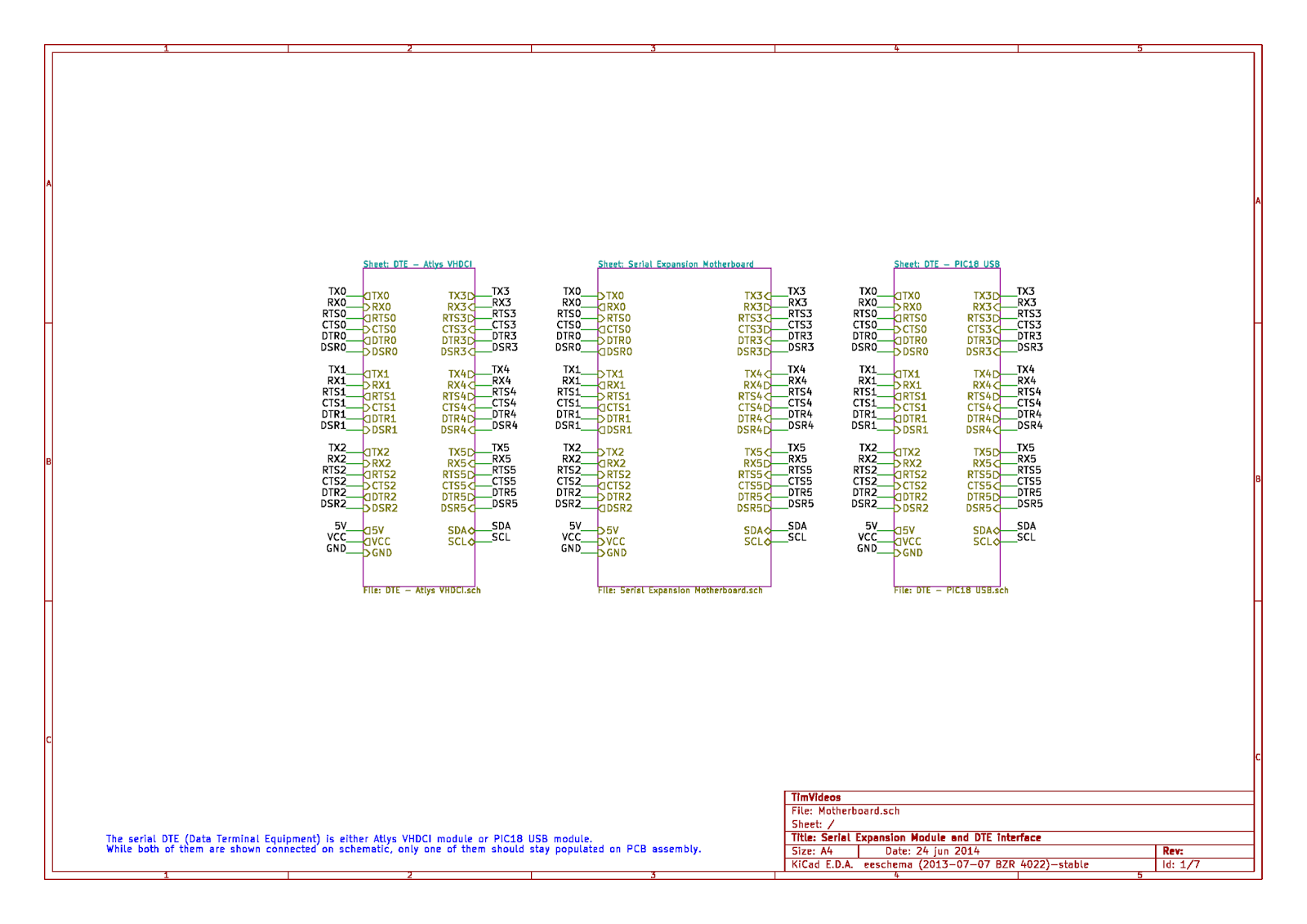
This is the topmost sheet of the motherboard schematic. All the serial expansion functionality has been abstracted from the specifics of the implementation. This allows the serial expansion circuit design to be added like a component to another schematic project. The serial expansion sheet is connected (through labels) in this schematic to Atlys VHDCI as well as PIC18F85J94 based interface. These two interfaces are called data equipment terminal, a common term used in serial communication, which is quite similar to ‘host’ in USB or ‘master’ in SPI/I2C. On the actual PCB assembly, only one of these DTE interfaces would be populated.
The VHDCI sheet:
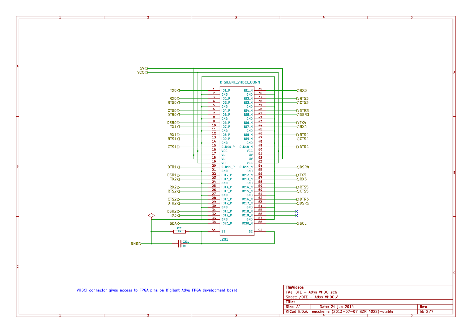
This sheet handles connector mappings and shield coupling. Going up again and taking a look into the PIC18 USB sheet:
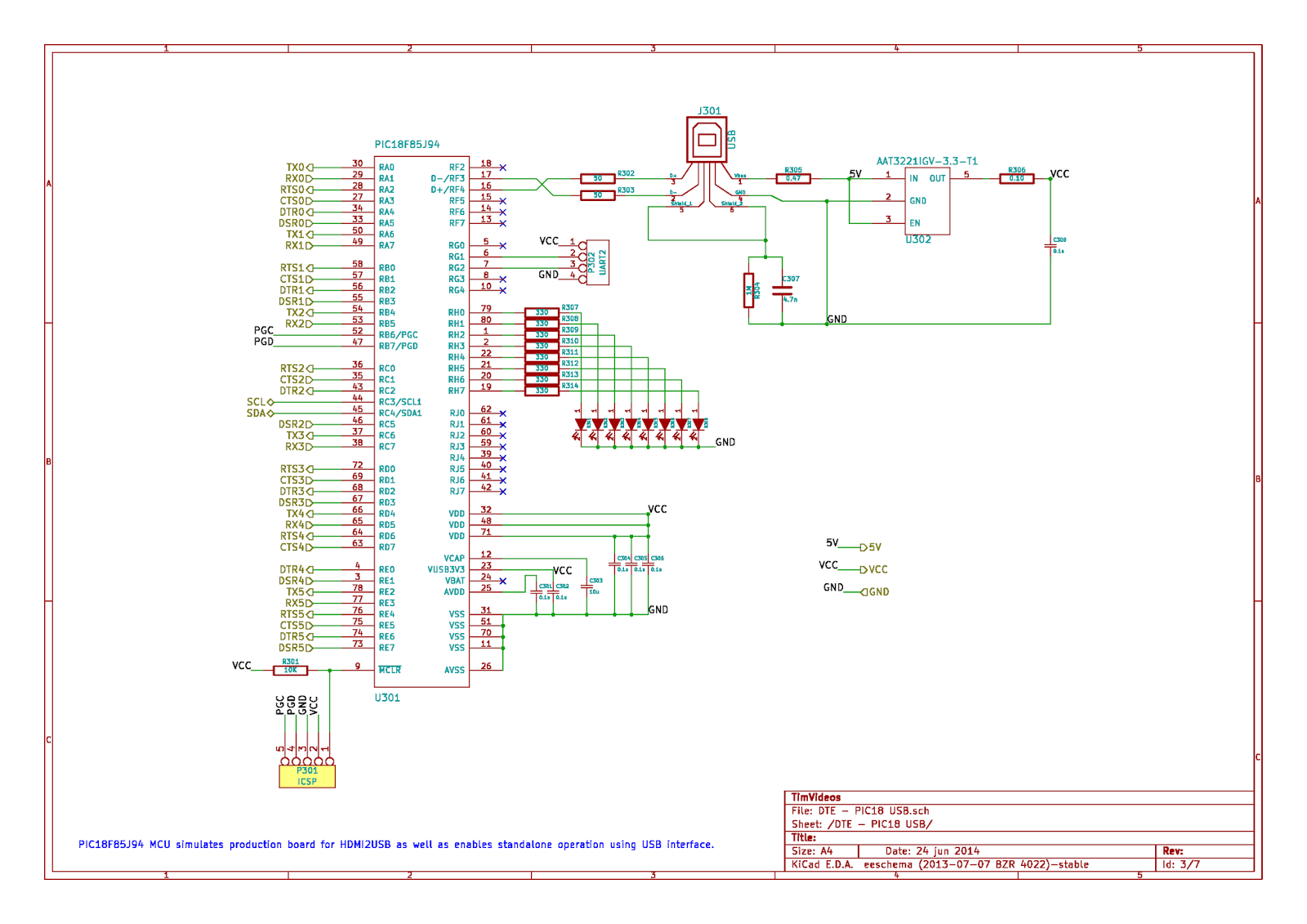
Here we find the microcontroller that is being planned to use in the production board. Also, pads for 8 LEDs and UART header are being given for debugging.
The serial expansion board also integrates full electrical isolation of device side. There’s a power isolation module and data isolation module. The data isolation also performs level-shifting from 3.3V to isolated 5V.
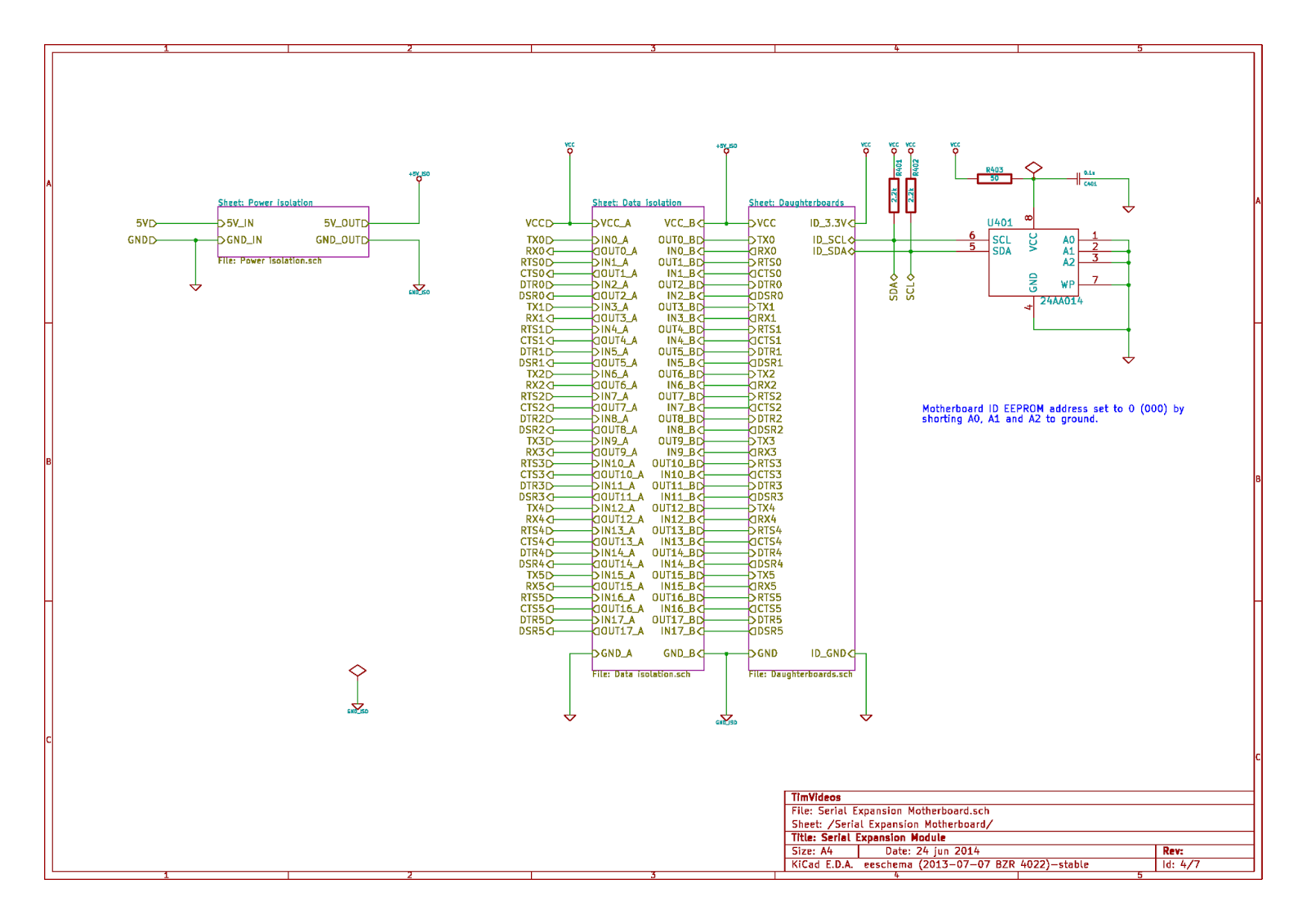
An EEPROM with slave address 0 is connected which contains the expansion board’s ID. This helps the Atlys board to identify that a serial expansion board is connected when the VHDCI interface is used. When the serial expansion board is detected, the logic would scan for higher slave addresses up to 7 to find daughterboards. The daughterboards would share this I2C bus and have differently addressed EEPROMs.
Note that EEPROMs are not electrically isolated from Vcc because they are not electrically connected in anyway to the actual daughterboard circuits.
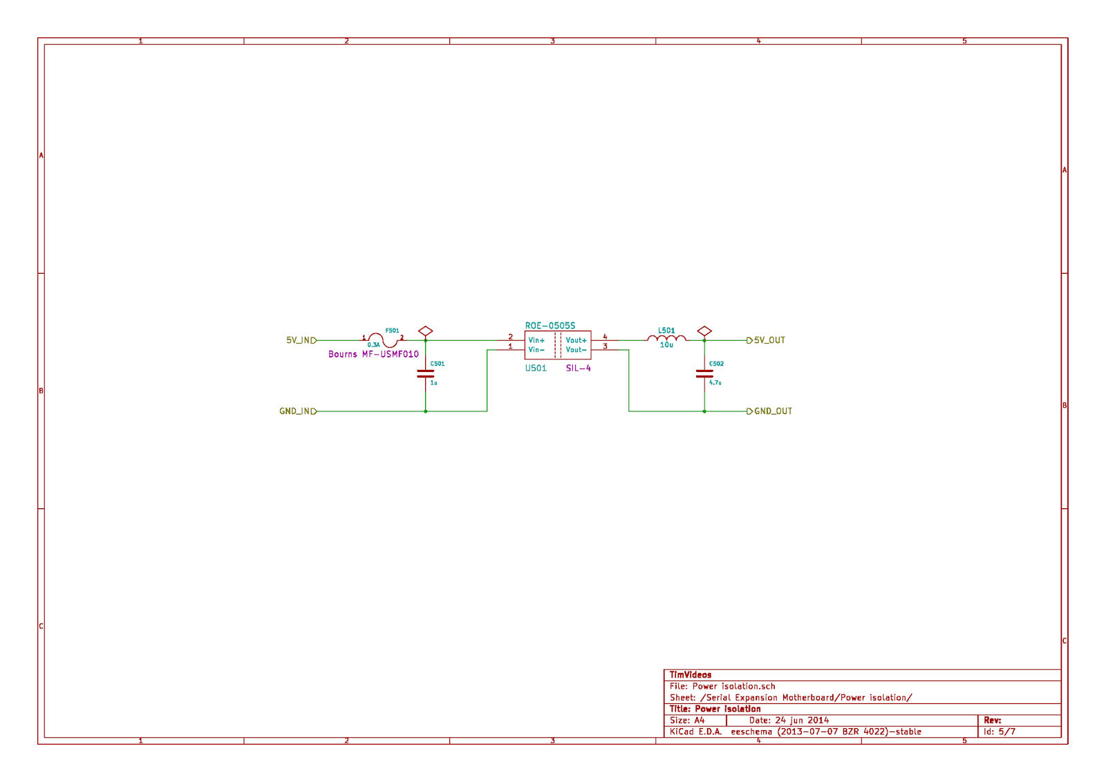
The power isolator uses ROE-0505S isolated DC-DC conversion module. The fuse is a resettable PTC fuse and LC filter at output stage filters out switching noise.
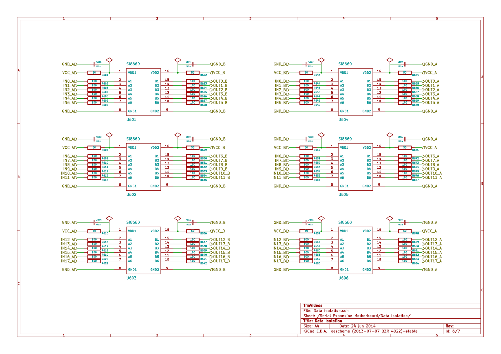
Data isolation sheet may look confusing, but these are unidirectional digital isolators arranged to give data isolation to 6 serial ports, each having 6 unidirectional signals lines (3 in and 3 out). Post-fix A refers to DTE side and post-fix B refers to daughterboard side.
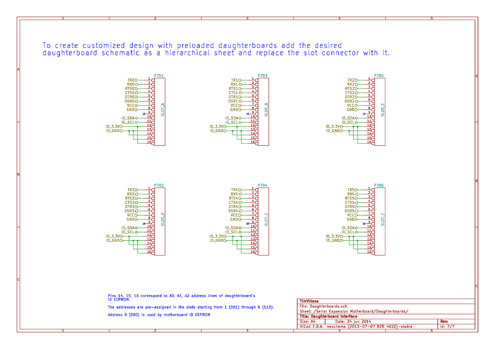
The above sheet is more interesting that it looks. Here we connect the isolated signals and power line to the daughterboard header (slot), but we can also connect them directly to daughterboard circuits by adding a daughterboard circuit as a hierarchical sheet. This would be useful if a customized serial expansion board need to be designed that comes preloaded with certain daughterboards.
There will be a few more revisions in the above schematic. We may need to find an alternative to I2C EEPROM auto-detection method if that doesn't fit all requirements. My schematic can be found in my repository.
This is all for now, my plans for next week would be:
- Completing daughter board designs. Get Tim to agree on the schematics.
- Starting with Motherboard PCB. Change any mechanical specifications if needed, get Tim to review and iterate.
- Same with the daughterboards. Get production files ready.
- The requirements documentation is outdated at the moment, it needs *huge* updates.
